How Do You Commission a TVRO Antenna? A Checklist for Yards and Integrators
Commissioning starts with a drilling drawing. What must be true before the ACU is energised, what a tracking test proves, and what the handover file needs.
- Author
- TVROVSAT Marine Engineering
- Date
- Read
- 7 min
What has to be true before commissioning day?
The base plate has to be drilled and stiffened, the cable run finished with every gland facing down, the shield bonded at one point, and both cable ends labelled with the equipment tag. Everything else — the controller, the satellite list, the receiver — is the last few hours of that job, not the first.
It is easy to treat commissioning as an event with its own start time. The documented schedule is a day of mechanical work for the antenna once the plate exists, plus the cable run and the commissioning itself — which is why most problems found on the day turn out to be installation problems rather than controller problems.
The drawing side of that work has its own note: how to read a base plate drilling pattern covers the envelope, the bolt circle and the cable entry in the order a yard should read them. What matters at this point is the consequence — the plate and the gland decide what the technician can achieve on the day.
What does the ACU actually do during commissioning?
The antenna control unit powers the stabilized antenna, holds the satellite parameters and hands the L-band signal to the receiver. Both versions are configured manually at the unit, so the procedure on the day is the same for Basic and Advanced; the difference is what can be changed later without sending somebody to the vessel.
The Antenna Control Unit (ACU) — Basic and Advanced is a rack-mounted unit that sits with the receiver and the multiswitch, and the catalogue documents the difference between the two versions as four functions:
| Function | Basic ACU | Advanced ACU |
|---|---|---|
| Setting manually | Yes | Yes |
| Setting by webpage | No | Yes |
| Data monitoring in cloud | No | Yes |
| Vessel route tracking | No | Yes |
The table is short on purpose. On a single vessel working one footprint, the Basic unit does everything commissioning asks of it. The Advanced unit earns its place when one office looks after several ships, or when a satellite or route change should be a setting rather than a visit — the Basic vs Advanced ACU comparison puts the same four lines next to the vessel types they suit.
Two details matter on the day itself. First, the range is commissioned from the ACU by a technician working from the manual — the vessel does not need factory engineers on board, which is what makes a short yard period viable. Second, on a two-dish vessel the wiring is the commissioning document: a switch between the antennas, the ACU and the receivers lets each receiver be pointed at either dish, and that switch should be ordered with the ACU so the harness arrives complete.
How do you prove the antenna is tracking?
You prove it against motion rather than against a picture at the berth. Both series are specified across roll ±25°, pitch ±15° and yaw ±8° at a 6-second period, with a tracking rate above 90°/s, so the meaningful test is a turn, a beam sea and a sector where the vessel's own superstructure blocks the sky.
A berth test is still worth doing, but it only proves the electronics: the unit acquires, the receiver locks, the cabin televisions get picture. What it cannot prove is the mount, and the mount is what the sea trial is for.
Watch three things once the vessel moves. Does the antenna re-acquire cleanly after a hard turn, or does it hunt before it settles? Does the picture survive the moment the dish sweeps past the radar mast? And on a hull that heels for long periods — a sailing yacht, an expedition vessel — does the geometry stay correct, or does the picture degrade in a way that a re-point clears?
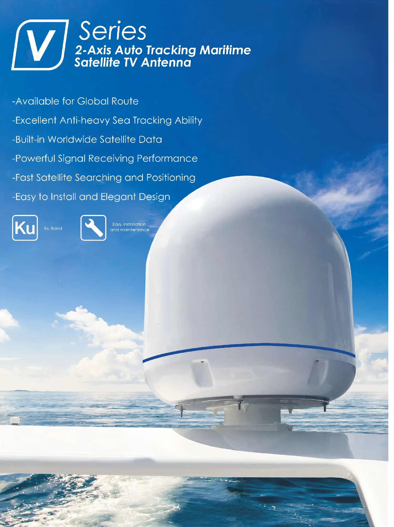
The X Series answers the last question with a third stabilization axis, elevation from −5° to 115° and a cross-level range of ±35°; the 3-axis maritime TVRO antenna page carries those figures next to the radome sizes and the tracking envelope. On a coastal ferry with modest roll the V Series is the economic answer, and a sea trial in ordinary weather usually confirms it.
Which checks get skipped, and what do they cost?
Four are skipped on almost every project: the drip loop under the gland, the service loop long enough to lift the radome without cutting the cable, the bond at one point rather than two, and labels that carry the equipment tag. Each costs minutes on the day and a survey finding later.
- 01Gland facing down or sideways-down, with a drip loop below it — a gland on a horizontal surface is a cup.
- 02Service loop of 300–500 mm at the radome, so the unit can be lifted without cutting the cable.
- 03Shield bonded at one point only: a bond at both ends makes a loop that carries circulating current through the coax.
- 04Antenna cable separated from power runs — crossing at right angles is acceptable, several metres of parallel run is not.
- 05Both ends labelled by equipment tag, so the label survives the next refit — "ACU-1 IN" rather than "antenna".
- 06Route surveyed at full roll and pitch: what clears at the dock may foul at sea.
The deck cabling and grounding note expands each of those into practice, including what to do where a parallel run with power cannot be avoided. A commissioning that stops at "the picture is up" leaves all six to the next survey, and the cost is rarely the part — it is the yard period needed to reach the part.
What goes in the handover file?
The satellites actually commissioned, the parameters written into the ACU, the ACU version and its settings, the drilling pattern and clearance envelope for the unit fitted, the switch logic where two antennas are installed, and the distribution scheme with the sea-trial record.
Two entries are habitually missing. The first is the satellite list — not the ones in the brochure, the ones the vessel will watch on its route; a later argument about coverage is almost always an argument about that list. The second is the switch logic, because a dual-antenna system nobody wrote down is a system that gets bypassed the first time it switches automatically and nobody recognises the indication.
The distribution scheme belongs in the same file because it decides what the crew can do next. The maritime IPTV and CATV headend page documents both routes — on the CATV side up to 58 channels, with left and right polarization carrying different channel sets so the services do not interfere, and on the IPTV side menu customization, user management, a dynamic boot screen, information insertion and catch-up playback. Whatever is fitted, the handover file should say which route is live and what a single-cabin failure looks like.
Frequently asked questions
Does the antenna have to be commissioned by the manufacturer?
No. The range is commissioned from the ACU by a technician with the manual, so a yard or a local service partner can do it. What the procedure does depend on is the mounting and the cable run being done to the drawing, because most commissioning problems turn out to be installation problems.
How long does commissioning take?
The documented figure is a day of mechanical work for the antenna once the plate exists, plus the cable run and the commissioning. What sets the schedule is the cable route and the mounting structure — yard items that belong in the dock plan rather than in the equipment order.
Can it be done at the berth?
The electronics can: acquisition, receiver lock and picture can all be proved alongside. Tracking cannot, because a berth has no motion and usually has a crane or a shed in the sky view. Plan the tracking test for the sea trial, with somebody aboard who can watch the screen while the vessel turns.
Do we need the Advanced ACU to commission the system?
No. Both versions are configured manually at the unit, so the procedure is identical. Advanced adds webpage configuration, cloud data monitoring and vessel route tracking — functions that matter after handover, not during it.
What should the yard hand over besides a picture?
The handover file: satellite list, ACU parameters and version, drilling pattern and clearance envelope, switch logic where two antennas are fitted, the distribution scheme, and a record of what the sea trial actually showed. That file is what makes the next service visit a repair rather than a survey.
Send the mounting position, the deck drawing and the satellites on the route, and we return the drilling pattern, the clearance envelope and the ACU configuration for the unit you are fitting — contact us with the route and the model, and the commissioning conversation starts from drawings instead of assumptions.
Related hardware
More engineering notes