How to Read a Base Plate Drilling Pattern Before the Yard Starts
The drilling drawing is the one document that turns an antenna order into a deck modification. Read it in the right order and the yard gets it right first time.
- Author
- TVROVSAT Marine Engineering
- Date
- Read
- 5 min
What the drawing is for
A TVRO antenna arrives with a base flange and a drawing that locates the bolt holes, the cable entry and the clearance envelope. The yacht or the yard uses it to drill the deck or the mast top before the unit arrives — which is why an error here is not a delivery problem but a steel problem.
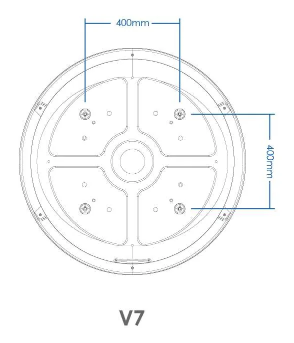
The catalogue publishes these drawings per family: a 400 mm bolt circle on the V7 base flange, a 305 mm pattern on the circular base plate supplied with the X Series installation, and the overall radome envelope alongside them. Read them together, not one at a time.
The order that works
- 01Overall envelope first. A 75 cm radome is 82 × 86 cm overall; a 105 cm unit is 123 × 137 cm. That decides whether the position exists at all, before any hole is marked.
- 02Then the bolt circle. The flange diameter and the hole pattern tell the yard what plate to prepare and where the fasteners land relative to structure below.
- 03Then the cable entry. A single G3/4 entry on most of the range — and its position relative to the flange decides which way the cable run leaves, which decides where the gland and the drip loop go.
- 04Then the service clearance. The drawing shows the radome; the human being who has to reach the connectors needs space the drawing does not dimension. Add it on site.
Three things that go wrong
The plate is drilled to the wrong model. The drawings are per model, and the difference between a 64 cm and an 85 cm unit is not cosmetic — the bolt circle and the envelope both change.
The deck beneath is not stiff enough. A base plate spreads load into the structure; if there is a single skin or a void under the position, the plate becomes a lever. That is a structural drawing question, and it should be answered before the drill.
The cable entry is drilled where the drawing puts it, and the drip loop then runs uphill. Water follows cable. The entry position in the drawing assumes a sensible route; if the actual route is different, the entry moves.
What to send us instead of guessing
Send the mounting position, the deck drawing and the model — we return the matching drilling pattern and the clearance envelope for that unit, so the yard can drill once. It is the cheapest hour in the whole installation.
Related hardware
More engineering notes