How to Size a TVRO Antenna for a Vessel: What Minimum EIRP Actually Tells You
Buyers size a TVRO antenna by physical diameter. The number that decides whether the picture holds is minimum EIRP — and it moves the other way.
- Author
- TVROVSAT Marine Engineering
- Date
- Read
- 7 min
The mistake: choosing by dish size
Almost every TVRO problem reported on a vessel traces back to one of two things: the antenna was sized against the wrong footprint, or the mounting could not give the antenna a clear view of the satellite. Neither is fixed by buying a bigger dish afterwards.
Dish diameter matters because it sets gain, and gain decides how weak a satellite signal the antenna can still work with. In our specification sheets that relationship is stated directly as minimum EIRP — the weakest downlink, in dBW, that the antenna can hold.
The numbers, in order
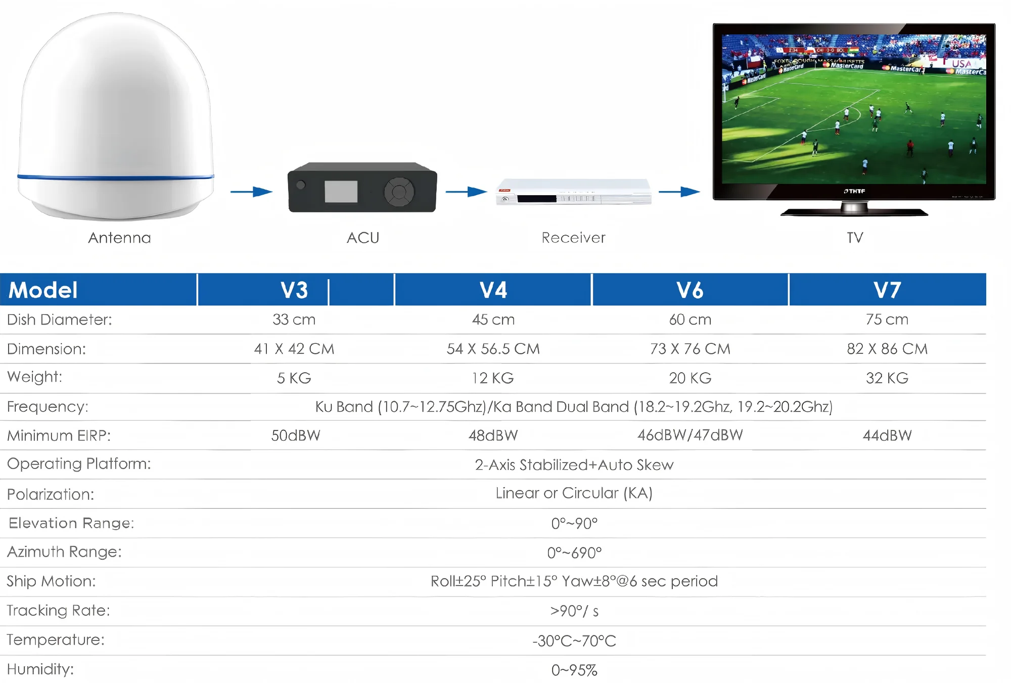
Here is the V Series progression. It is worth reading as a ladder rather than as four separate products:
| Model | Radome | Weight | Minimum EIRP |
|---|---|---|---|
| V3 | 33 cm | 5 kg | 50 dBW |
| V4 | 45 cm | 12 kg | 48 dBW |
| V6 | 60 cm | 20 kg | 46 / 47 dBW |
| V7 | 75 cm | 32 kg | 44 dBW |
Each step down in dBW is a step up in what the antenna can survive. The X Series continues the ladder: X6 at 64 cm needs 46 dBW, X8 at 85 cm needs 43 dBW, and X10 at 105 cm needs 41 dBW.
Why 2 dB matters
A five-decibel difference between a V3 and a V7 looks small until you put it next to the footprint contour map of the satellite you intend to watch. On a typical Ku broadcast footprint the contour lines near the edge of coverage are often only a couple of dB apart, and the vessel spends real time inside those outer contours — at the northern end of a route, or in the fringe of a beam pointing at a neighbouring region.
An antenna with 6 dB more margin than the weakest point of its route stops producing "it works in port and drops at sea" calls. That is the whole argument for specifying from the contour map with a margin, rather than from the physical size that fits the mast.
The other half: can the mount follow?
Margin only helps if the antenna stays pointed. Both series document the same ship-motion envelope — roll ±25°, pitch ±15°, yaw ±8° at a 6-second period — with a tracking rate above 90°/s. The X Series adds a third stabilization axis, auto-skew, elevation from −5° to 115° and a cross-level range of ±35°.
On a coastal ferry with modest roll, a 2-axis platform is enough. On a vessel that heels hard or spends days on a slow, deep roll, the third axis is what stops the dish from trading elevation error for azimuth error every time the hull comes back.
A short specification procedure
- 01List the satellites you actually intend to watch along the route, not just at the home port.
- 02Note the weakest EIRP contour the vessel will sit inside, and subtract 3 dB of rain and pointing margin.
- 03Pick the smallest model whose minimum EIRP is below that number.
- 04Check the weight against the mast or hardtop and confirm the mounting position has a clear view.
- 05Only then decide between Basic and Advanced ACU — the ACU does not add signal margin, it adds configurability.
If steps 1–3 are unknown, send us the route and the satellite names. Sizing from the footprint is a five-minute conversation; re-rigging a mast is not.
Related hardware
More engineering notes